
Measurement of Capacitance by Schering Bridge 
Theory
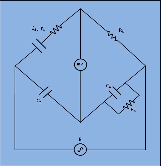
Fig 1: Circuit diagram for measurement of Capacitance by Schering Bridge
C1=capacitor whose capacitance is to be measured.
r1= a series resistance representing the loss in the capacitor C1.
C2= a standard capacitor.
R3= a non inductive resistance.
C4= a variable capacitor.
R4= a variable non inductive resistance.
At balance,
$$ (r_1+\frac{1}{j \omega C_1}) * (\frac{R_4}{ j \omega C_4R_4+1}) = \frac{R_3}{j \omega C_2}......(1) $$
$$ r_1R_4-\frac{jR_4}{\omega C_1} = - \frac{jR_3}{\omega C_2} + \frac{R_3R_4C_4}{C_2}......(2) $$
Or Equating the real and imaginary terms in equa. (2), we obtain
$$ r_1 = R_3*\frac{C_4}{C_2}......(3) $$
$$ C_1 = R_4* \frac{C_2}{R_3}......(4) $$
And, Two independent balance equations (3) and (4) are obatined if C4 and R4 are chosen as the variable elements.Dissipation factor
$$ D_1 = \omega C_1r_1......(5) $$