
Three Phase Power Measurement 
Theory

Fig 1: Connection diagram for three phase power measurement using two wattmeter method
The connection diagram for the measurement of power in three phase power measurement circuit using two wattmeter's method is shown in figure 1. This is irrespective of the circuit connection star or delta. The circuit may be taken as balanced or unbalanced one, balanced type being only a special case. Please note the connection of two wattmeter's. The current coil of the wattmeter's 1 and 2 in series with R and B phase with the pressure voltage coils being connected across R-Y and B-Y respectively. Y is the third phase in which no current coil is connected.
If star connected circuit is taken as an example the total instantaneous power consumed in the circuit is,
$$W= I_{RN}*V_{RN} + I_{YN}*V_{YN} + I_{BN}*V_{BN} ...(1)$$
Each of the terms in the above expression equation (1) is the instantaneous power consumed by the phases. From the connection diagram, the circuit in and the voltages across the respective (current, pressure or voltage) coils in the wattmeter, W1 are
IRN and $$V_{RY} = V_{RN} - V_{YN}$$.
So, the instantaneous power measured by the wattmeter W1 is $$W_1 = I_{RN}*V_{RY}$$.
Similarly the instantaneous power measured by the wattmeter W2 is . $$W_2 = I_{BN}*V_{BY} = I_{BN}* (V_{BN} - V_{YN})$$
Some of the two readings as given above is,
$$W_1 + W_2 = I_{RN} ( V_{RN} - V_{YN} ) + I_{BN} ( V_{BN} - V_{YN} )$$
$$ = I_{RN} V_{RN} + I_{BN} V_{BN} - V_{YN} ( I_{RN} + I_{BN} ) ....(2)$$
$$and \ I_{RN} + I_{BN} + I_{YN} = 0$$
$$applying \ in \ equation \ (2),$$
$$W_1 + W_2 = I_{RN} V_{RN} + I_{BN} V_{BN} + V_{YN} I_{YN} .....(3)$$
Equation (1) is compared with equation (3) to give the total instantaneous power consumed in the circuit . They are found to be same. The phasor diagram of three phase balanced star connected circuit is shown in figure 2.
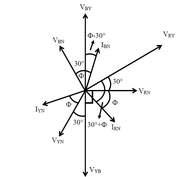
Fig 2: Phasor diagram of three phase balanced star connected circuit