
Measurement of Capacitance by Wien Series Bridge 
Theory
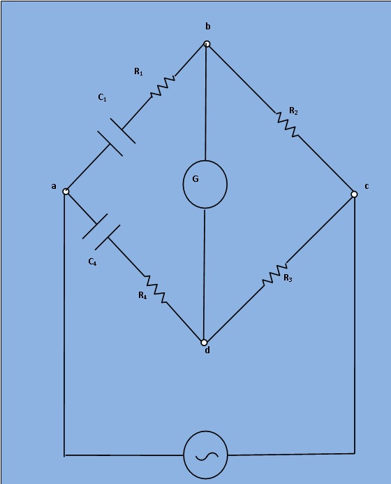
Fig.1 : Circuit diagram for measurement of capacitance by Wien Series Bridge
Let,
C1= Capacitor whose capacitance is to be measured,
R1= A series resistance representing the loss in the capacitor C1,
C4 = A standard capacitance with series resistance of R4,
R2 and R3 = Non-inductive resistances.
At balance,
$$(R_1 +\frac{1}{(jωC_1)}) * R_3 = (R_4 + \frac{1}{ (jωC_4)}) * R_2 ..........(1)$$
$$R_1R_3+\frac{R_3}{jωC_1}=R_2R_4+\frac{R_2}{jωC_4} ..........(2)$$
Equating the real and imaginary terms,
$$R_1R_3=R_2R_4$$ $$R_1=\frac{R_2R_4}{R_3}$$ and , $$ \frac{R3}{jωC1}= \frac{R2}{jωC4} $$ $$C_1=\frac{C_4R_3}{R_2}$$
If the bridge in Fig.1 is used to measure capacitance , it may be written as
$$C_1=\frac{C_4R_3}{R_2}..........(3)$$
$$R_1=\frac{R_2R_4}{R_3}..........(4)$$
The dissipation factor of capacitance C1 is defined as,
$$D_1=ωC_1R_1..........(5)$$
While in measurement of capacitance C1 , R1 is not a separate unit but represents the equivalent series resistance of the capacitor and thus can be determined in terms of the elements of the bridge.