
Determination of different parameters of Two-port network and verification of their interrelations 
Procedure
Circuit Diagram:
.jpg)
[Fig 1: Circuit Diagram for M network]
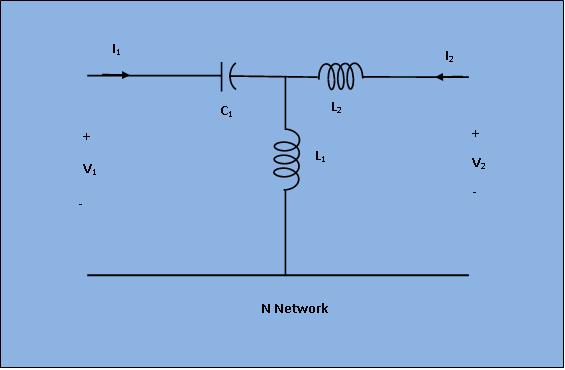
[Fig 2: Circuit Diagram for N network]
Cascading Mode Circuit Diagram:
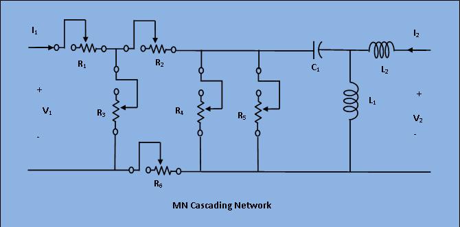
[Fig 3: Circuit Diagram for MN cascading network]
- Enter the supply voltage and frequency.
- Enter the values of R,L,C (in M/N network).
- Select the desired network by choosing the corresponding tab( M/ N/ MN )tabs.
- Under "Controls" Choose the desired network parameter (Z / Y / h / ABCD) in "Parameter Select".Respective instruction box will be appeared.Follow them to find out respective parameter values. For ex:-
Z-Parameter Case 1: Obtaining the values of Z11 and Z21
i)Apply Power to Input port and set Output port to Intermediate.
ii)Switch on the supply and click on "Simulate" button.
iii)Observe the result Z11=V1/I1 and Z21=V2/I1 when I2=0.
iv)Switch off the supply.
Case 2: Obtaining the values of Z12 and Z22
i) Apply Power to Output port and set Input port to Intermediate
ii)Switch on the supply and click on "Simulate" button
iii)Observe the result Z12=V1/I2 and Z22=V2/I2 when I1=0
iv)Switch off the supply.
Similerly check for Y,ABCD,h parameter for M,N,MN networks.