
Determination of different parameters of Two-port network and verification of their interrelations 
Theory
Consider a passive two-port (4-terminal ) network as shown in figure 1.
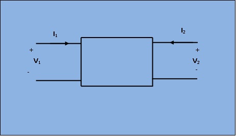
Fig.1 : Circuit diagram
The voltage V1, V2 and current I1, I2 can be related in terms of Z-parameters as shown below.
$$\begin{gather} \begin {bmatrix} V_1 \\ V_2 \end {bmatrix} = \begin {bmatrix} Z_{11} & Z_{12} \\ Z_{21} & Z_{22} \end {bmatrix}* \begin {bmatrix} I_1 \\ I_2 \end{bmatrix} \end{gather}$$
where,
$$ Z_{11} = ( \frac { V_1 } { I_1 } )_{ I_2 = 0 } \quad Z_{12} = ( \frac { V_1 } { I_2 } ) _ { I_1 = 0} $$
$$ Z_{21} = ( \frac { V_2 } { I_1 } )_{ I_2 = 0 } \quad Z_{22} = ( \frac { V_2 } { I_2 } ) _ { I_1 = 0} $$
Similarly, current I1 and I2 can be expressed in terms of volatge V1 and V2 using Y parameters.
$$\begin{gather} \begin {bmatrix} I_1 \\ I_2 \end {bmatrix} = \begin {bmatrix} Y_{11} & Y_{12} \\ Y_{21} & Y_{22} \end {bmatrix} * \begin {bmatrix} V_1 \\ V_2 \end {bmatrix} \end{gather}$$
where,
$$ Y_{11} = ( \frac { I_1 } { V_1 } )_{ v_2 = 0 } \quad Y_{12} = ( \frac { I_1 } { V_2 } ) _ { V_1 = 0} $$
$$ Y_{21} = ( \frac { I_2 } { V_1 } )_{ v_2 = 0 } \quad Y_{22} = ( \frac { I_2 } { V_2 } ) _ { V_1 = 0} $$
Similarly, voltage V1 and current I2 can be expressed in terms of current I1 and voltage V2 using h parameters as below.
$$\begin{gather} \begin {bmatrix} V_1 \\ I_2 \end {bmatrix} = \begin {bmatrix} h_{11} & h_{12} \\ h_{21} & h_{22} \end {bmatrix} * \begin {bmatrix} I_1 \\ V_2 \end {bmatrix} \end{gather}$$
where,
$$ h_{11} = ( \frac { v_1 } { I_1 } )_{ v_2 = 0 } \quad h_{12} = ( \frac { V_1 } { V_2 } ) _ { I_1 = 0} $$
$$ h_{21} = ( \frac { I_2 } { I_1 } )_{ v_2 = 0 } \quad h_{22} = ( \frac { I_2 } { V_2 } ) _ { I_1 = 0} $$
Lastly, voltage V1 and current I1 can be expressed in terms of volatge V2 and current (-I2) using ABCD parameters.
$$\begin{gather} \begin {bmatrix} V_1 \\ I_1 \end {bmatrix} = \begin {bmatrix} A & B \\ C & D \end {bmatrix} * \begin {bmatrix} V_2 \\ -I_2 \end {bmatrix} \end{gather}$$
where,
$$ A = ( \frac { v_1 } { V_2 } )_{ I_2 = 0 } \quad -B = ( \frac { V_1 } { I_2 } ) _ { V_2 = 0} $$
$$ C = ( \frac { I_1 } { V_2 } )_{ I_2 = 0 } \quad -D = ( \frac { I_1 } { I_2 } ) _ { V_2 = 0} $$
Cascading Mode Circuit Diagram:
Circuit diagram for cascading mode is shown in figure 2.
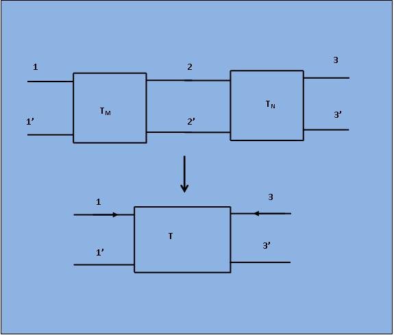
Fig.2 : Circuit Diagram for Cascading Mode
If two networks M and N connected in cascade then the total transmission matrix T of the overall network is given by,
$$T = T_M * T_N$$