
Verification of Compensation Theorem 
Procedure
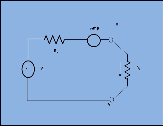
[Fig.1 The circuit diagram for verification of Compensation Theorem]
case 1: Set the voltage (say V1=100V), internal resistance (say Rint=50ohm) and load resistance (RL). Simulate the circuit and observe the current I.
case 2: Change RL by ΔRL. ΔRL can change upto `+-2%` of RL. Simulate the circuit and observe the load current (I').
case 3: Simulate the circuit. Observe the varying current (difference between case 1 and case 2) in compensating circuit.