
Verification of Norton Theorem 
Theory
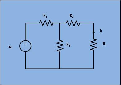
A linear active network consisting of independent and(or) dependent voltage and current sources and linear bilateral network elements can be replaced by an equivalent circuit consisting of current sources in parallel with the resistance, the current source being the short circuited current across the load terminal and resistance being the internal resistance of the source network looking through the open circuited load terminals. In order to find the current throughRL, the load resistance of the figure 1 by Norton's theorem, let,replace RL by short circuit as shown in figure 2.
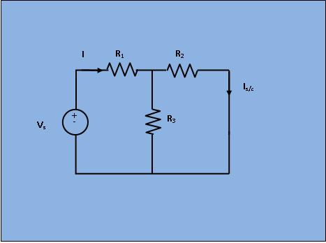
Obviously, in Fig 2;
$$I=\frac{V_s}{R_1+\frac{R_2 * R_3}{R_2 + R_3}}$$
$$I_{s/c}= I\frac{R_3}{R_3 + R_2}$$
Next, the short circuit is removed and the independent source is deactivated as shown in figure 3.
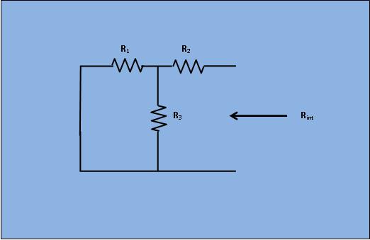
From Fig 3;
$$R_{int}= R_2+ \frac{R_1*R_3}{R_1+R_3}$$
As per Norton's theorem , the equivalent circuit as shown in figure 4, would contain a current source in parallel to the internal resistance, the current source being the short circuited current across the shorted terminals of the load resistor.
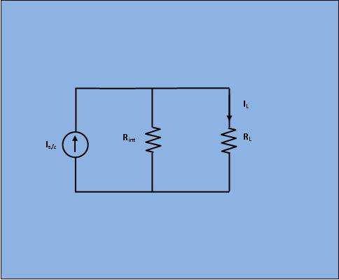
Obviously, from Fig 4;
$$I_{L}= I_{s/c}\frac{R_{int}}{R_{int}+R_L}$$