
Verification of Thevenin Theorem 
Procedure
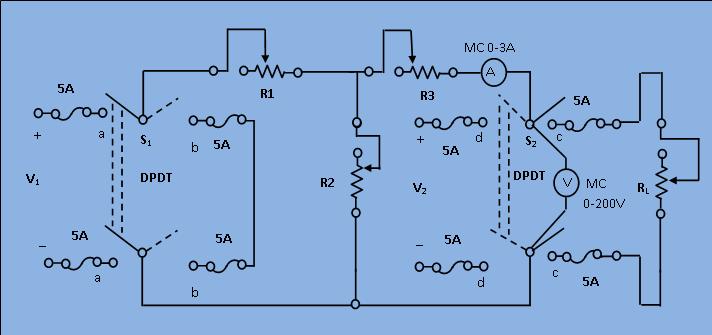
1) Keep all the resistance close to their maximum respective values.
2) Close the switch S1 to "aa" and S2 to "cc" positions. Observe the load current (IL) and voltage (VL) readings. The load resistance
$$R_{L}=\frac{V_L}{I_L}$$
3) Remove the load by opening the switch S2 and read the open circuit voltage (or Thevenin equivalent voltage) Vth.
4) Next, compute the resistance (RTH) of the network as seen from the load terminals,
a) Replace the 220 V source by a short by closing S1 to "bb".
b) Apply 110 V at the output terminals by closing S2 to "dd". Read the voltmeter (V) and ammeter (I) and get
$$R_{th}=\frac{V}{I}$$
5) Now compute the load current. Applying Thevenin theorem
$$I_{L}=\frac{V_{th}}{R_{th}+R_{L}}$$
6) Compare the above computed load current with its observed value in step (2) and verify the theorem.