
Verification of Thevenin Theorem 
Theory
Its provides a mathematical technique for replacing a given network, as viewed from two terminals, by a single voltage source with a series resistance. It makes the solution of complicated networks quite quick and easy. The application of this extremly useful theorem will be explained with the help of following simple example.
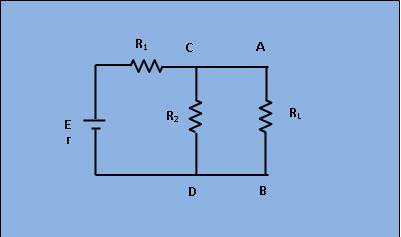
Fig.1 : Circuit with source E and Load RL
Suppose, it is required to find current flowing through load resistance RL, as shown in figure 1.
This expression proceed as under:
1) Remove RL from the circuit terminals A and B and redraw the circuit as shown in figure 2. Obviously, the terminal have become open circuited.
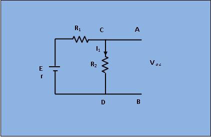
Fig.2 : Circuit with RL removed
2) Calculate the open circuit Voltages VO.C. which appears across terminals A and B when they are open .ie. when RL is removed.
As seen, V.O.C.= drop across R2= IR2 where I is the circuit current when A and B is open.
$$ I=\frac{E}{r + R_1+R_2} $$
$$ V_{o.c.}= I*R_2 $$
$$ V_{o.c.} = \frac{E*R_2}{r + R_1+R_2} $$
It is also called Thevenin voltage(Vth).
3) Now, imagine the battery to be removed from the circuit, leaving its internal resistance r behind and redraw the circuit as shown in figure 3.
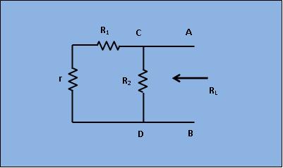
Fig.3 : Circuit with RL and E removed
When viewed inwards from the terminals A and B, the circuit consists of two parallel paths: one containing R2 and another containing (R1+r). The equivalent resistance of the network as viewed from these terminals is given as,
$$R_{th}=\frac{(R_1+r)*R_2}{R_1+r+R_2}$$
$$I_{1}=\frac{V_{th}}{R_{th}+R_L}$$
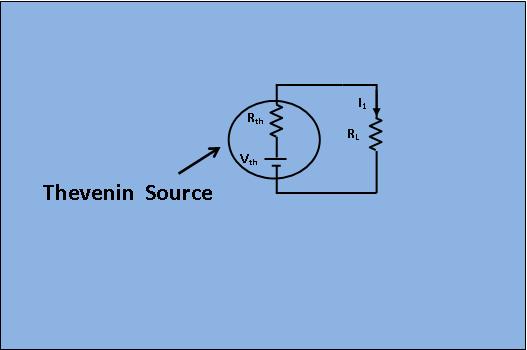
Fig.4 : Thevenin's equivalent circuit