
Measurement of Self Inductance by Maxwell Bridge 
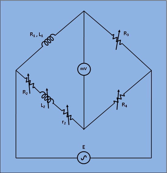
A Maxwell’s inductive bridge shown in figure below is used to measure an unknown inductance in comparison with known inductance. The values at balance R2= 590Ω, R4=60Ω, R3= 100Ω, r2=10Ω and L2= 2mH. Calculate the values of R1 and L1 . Calculate also the Q-factor of the coil if frequency is 1000Hz.
A galvanometer with a full scale current of 10 mA has a resistance of 1000Ω. The multiplying power (the ratio of measured current to galvanometer current) of 100 Ã�© shunt with this galvanometer is
A Maxwell’s inductive bridge shown in figure below is used to measure an unknown inductance in comparison with known inductance. The values at balance R2= 590Ω, R4=60Ω, R3= 100Ω, r2=10Ω and L2= 6mH. Calculate the values of R1 and L1 . Calculate also the Q-factor of the coil if frequency is 1000Hz.

The errors introduced by an instrument fall in which category ?