
Measurement of Self Inductance by Maxwell Bridge 
Introduction
To determine the self-inductance of an unknown coil.
Theory
This bridge circuit measures an inductance by comparison with variable standard self inductance. The connections for balance condition is shown in Fig. 1.
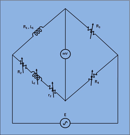
Fig 1: Circuit Diagram for Measurement of Self Inductance by Maxwell Bridge
Let, L1= Unknown self Inductance of resistance R1,
L2= variable inductance of fixed resistance r2,
R2= variable resistance connected in series with inductor L2,
R3,R4= known non inductive resistances,
At balance condition,
$$ (R_1 +j \omega L_1)*R_4 = (R_2 + r_2 + j \omega L_2)*R_3 ...(1) $$
Equating both the real and imaginary parts in eq.(1) and seperating them,
$$ L_1 =(\frac{R_3}{R_4})L_2 ...(2) $$
$$ R_1 = (\frac{R_3}{R_4})*(R_2+r_2) ...(3) $$
Resistors R3 and R4 are normally a selection of values from 10, 100, 1000 and 10,000Ω. r2 is a decade resistance box.