
Measurement of Self Inductance by Maxwell Bridge 
Procedure
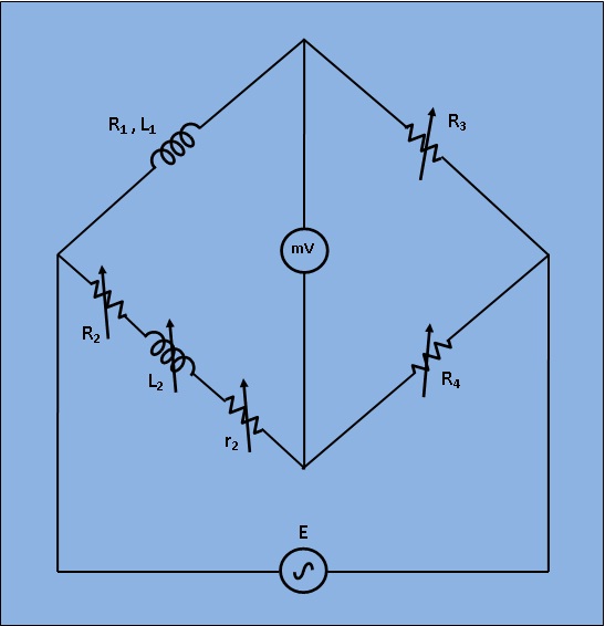
Fig 1: Circuit Diagram for Measurement of Self Inductance by Maxwell Bridge
- Apply Supply voltage from the signal generator with arbitrary frequency. ( V =3v). Also set the unknown Inductance value from 'Set Inductor Value' tab.
- Then switch on the supply to get millivoltmeter deflection.
- Choose the values of L2, r2, R2, R3 and R4 from the inductance and resistance box. Varry the values to some particular values to achieve "NULL".
- Observe the millivoltmeter pointer to achieve "NULL".
- If "NULL" is achieved, switch to 'Measure Inductor Value' tab and click on 'Simulate'. Observe the calculated values of unknown inductance (L1) and it's internal resistance (R1) of the inductor.
- Also observe the Dissipation factor of the unknwown inductor which is defined as
$$ \frac{\omega L}{R} \ Where, \omega=2 \pi f $$